Inferring the sender of a CAN frame
The latest update of the open source can2 protocol decoder is able to automatically infer the sender of a CAN frame. It uses the method of deterministic distortion of CAN signals that result in frames from a given node on the bus having consistently shortened or lengthened recessive pulses. The differences can be quite small - just 10 or 15 nanoseconds - but they can be picked up by a suitably accurate logic analyzer.
A few years ago I developed the decoder to show much more information about what’s happening on a CAN bus than the usual protocol decoders in logic analyzers. It already warns about unusual CAN events (such as like error frames, overload frames1, or a Double Receive2) which might be low-level CAN protocol attacks3. Upgrading it to automatically infer the sending node for each frame is incredibly useful. In particular, it means the decoder can passively analyze a CAN bus: there is no need to unplug nodes to see which frames no longer appear (which anyway disrupts the behavior of a running system). Because it maps CAN IDs to nodes it can help build up a detailed picture of a CAN system. This is useful for debugging (to see which node sends an unexpected CAN frame, for example), for reverse engineering an unknown system, and even for detecting spoof frames4.
Sigrok decoders
The can2 protocol decoder is written in Python for the Sigrok decoder API.
This means that all Sigrok-supported hardware can use the CAN decoder. In addition, some other hardware supports
Sigrok decoders. I have the DSLogic U3Pro32 that can
sample a channel at up to 1GS/sec, which gives a CAN pulse measurement accuracy of 1 nanosecond - easily
able to distinguish between senders (NB: DSView isn’t completely Sigrok-compatible but the can2 decoder works
around these changes and will work with both pure Sigrok and DSView tools).
The can2 protocol decoder isn’t part of the upstream distribution, so it has to be manually installed. The
files are in the CANHack GitHub repository in the
folder can2 (inside src) and the can2 folder should be copied
into the Sigrok decoder folder. For DSView under Windows, that decoder folder is:
1
C:\Program Files\DSView\decoders\
For Sigrok under Linux the decoder folder is:
1
~/.local/share/libsigrokdecode/
Running the decoder
The decoder is enabled by adding it and assigning a channel on the logic analyzer to CAN RX.
When starting (after a trigger has produced a trace), the decoder attempts to
read a node calibration file called can2nodes.json that specifies the timing distortions associated
with each known node. If no file is found then an empty calibration is assumed. After a trace capture,
the calibration data augmented with the contents of the trace (this might create new nodes if a decoded frame’s
distortion values don’t fit with known nodes). By default, the decoder will not update can2nodes.json
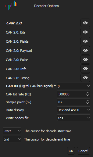
but if the decoder option Write nodes file is set to Yes then the file is overwritten (or created).

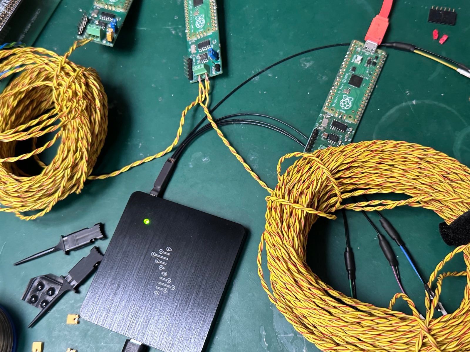
Newly observed nodes are named automatically as Node0, Node1 and so on. In the benchtop testing of the decoder there are three CANPico boards connected with FLRY-A twisted pair CAN cable.

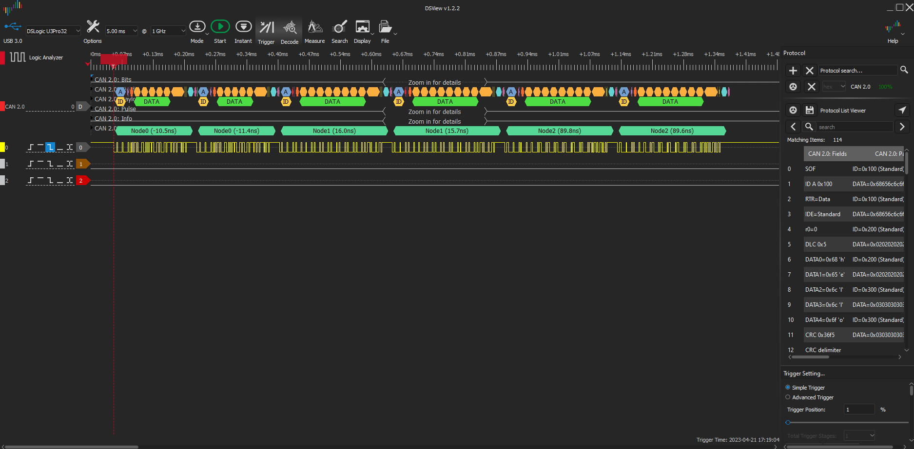
One of the boards sends a pair of CAN frames (both with ID 0x100) and the other boards each responds with two frames (one with IDs of 0x200 and the other with IDs of 0x300). The DSView logic analyzer is set to trigger (typically falling edge of the channel assigned to CAN RX with a pre-trigger buffer of at least 11 CAN bit times) and then armed. After seeing the CAN frames, it produces a trace that looks like this:

The decoder shows there are three different CAN nodes seen (and it has automatically named them Node0, Node1 and Node2). The time distortions are given after the node name. The first node has its recessive pulses lengthened by around 11ns. The individual recessive pulses within a CAN frame are also measured, and the details seen by zooming in to the trace. The details include the inferred sending node for each pulse (if no node is known then ‘?’ is displayed for the node name). This can be used to detect if an Error Passive Spoof Attack5 has been made.
The JSON file written looks something like this:
1
[{"first_ns": -12, "last_ns": -7, "name": "Node0"}, {"first_ns": 16, "last_ns": 17, "name": "Node1"}, {"first_ns": 89, "last_ns": 90, "name": "Node2"}]
The intention is that the file will be edited by hand, after sessions where new nodes are discovered, to give them more meaninful names to display. The file records the observed distortion ranges for each node and when inferring a frame, the decoder will measure the mean pulse distortion and then attempt to fit within the ranges of nodes. If there is more than one node then it will display all that match, but order the matches according to best fit.
Footnotes
-
The overload frame is a legacy feature of the protocol (and no modern silicon should generate it). The Freeze Doom Loop Attack exploits it to silently freeze the CAN bus. ↩
-
The ISO 11898 CAN standard specifies that a frame is received OK at the second-to-last EOF bit, but is sent OK at the last EOF bit, so an error in the last bit of EOF will result in the frame being received, then error handling, then the frame is sent again (and so received again). ↩
-
CAN protocol attacks are where malware takes direct control of the output port to the TX pin of the tranceiver and then sends carefully crafted signals to the bus to subvert the CAN protocol (the (CANHack toolkit)[https://canislabs.com/canhack/] contains software to implement proof-of-concept CAN protocol attacks). ↩
-
A spoof frame is one with an ID normally sent from another node, and is a common technique for hacking the CAN bus (the CAN Injection Attack used to steal cars is an example of a spoofing attack). ↩
-
An Error Passive Spoof Attack is a CAN protocol attack where a victim node has been driven into the error passive state and then after it has started transmitting its payload the attacker node overwrites it (under the CAN error rules, the victim cannot signal an error to stop this). ↩