
CAN bus wiring has a big effect on how fast data can go on CAN. CAN bits are normally 2000ns (2 microseconds, or 500kbit/sec) or longer for slower buses (a J1939 CAN bus runs at 250kbit/sec and can be up to 40m long). But CAN FD has the promise of much faster speeds on conventional CAN bus wiring, up to 8Mbit/sec (i.e. 125ns bit times). Yet most of the automotive industry is using CAN FD at just 2Mbit/sec or even slower. Why is this?
The answer is down to the bus wiring. There’s an excellent paper by Schreiner et al from the 2017 International CAN Conference that covers this topic. When a CAN bus isn’t perfectly impedance-matched by the standard CAN 120 ohm termination resistors at either end, there are reflections of the CAN signals. These can be negative (i.e. a positive pulse gives rise to a negative amplitude pulse) or positive (i.e. a positive pulse gives rise to a positive amplitude pulse). The reflection can be characterised by the reflection coefficient: a value of 0.5 means that the pulse reflected back is the same sign as the pulse hitting an end, but half the amplitude.
A reflected pulse moves back up the bus until it hits the other end, then reflects again. These reflections add together as an infinite geometric sum, giving the resulting signal for the transceiver. The net effect of this can be calculated using a bounce diagram.
The CAN transceiver determines if the signal is dominant (logic 0) or recessive (logic 1) by measuring the difference between the CAN H and CAN L lines, with a difference of more than 700mV equal to a dominant bit. Transceivers also apply a hysteresis function to prevent rapid state changes (typically 50mV).
From this it is possible to build a simple model and use that to understand how a CAN bus distorts signals, so I built a tool to explore the parameter space. The parameters the tool can change are:
- Bus length
- Transmitter position along the bus
- Receiver position along the bus
- Reflection coefficient of the bus
- Bit time
The tool has sliders for these parameters, plus a button to generate a new random fast bit sequence, which are followed by a few slower pulses to see how a classic CAN signal is affected (it’s possible to also use the tool to generate videos where a parameter is ‘walked’ through a range of values). So let’s do some exploring.
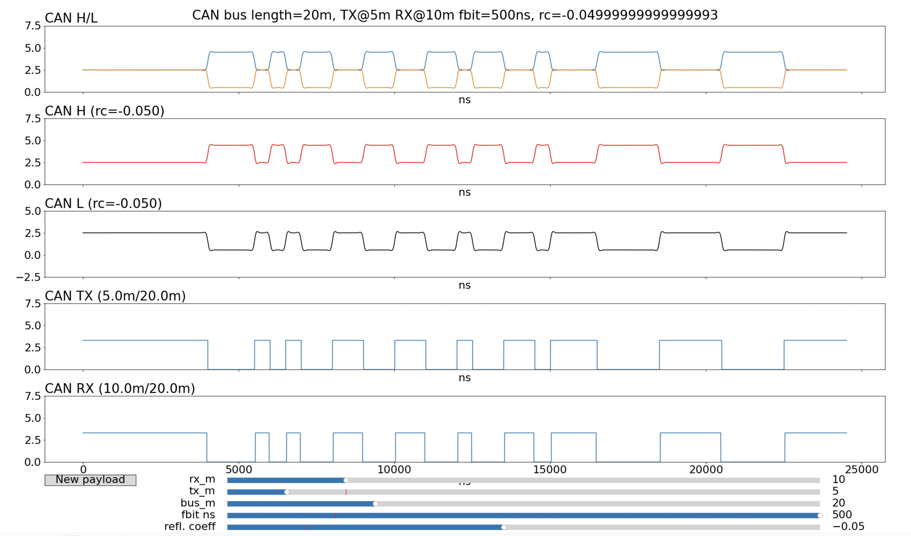
Let’s start with a 20m CAN bus with 2Mbit/sec bits (i.e. 500ns long), a transmitter at 5m and a receiver at 10m, where the bus wiring is of good quality with no major reflections. Figure 1 shows what we see from the model.
 |
|---|
| Figure 1: 20m CAN bus with a small reflection coefficient |
The tool screenshot shows the parameter sliders and various signals over 25 microseconds. The bottom two traces are the digital CAN TX at the transmitter and the CAN RX at the receiver (the traces are time shifted to eliminate the propagation delays so that a direct comparison can be made). The top line shows the CAN H and CAN L signals corresponding to the output of the transceiver. This is the ‘pure’ analog CAN signal without disturbances. Below it are the CAN H and CAN L traces that actually appear on the bus. Because this bus is a well-terminated bus there are minimal reflections and the resulting signal is close to the pure signal.
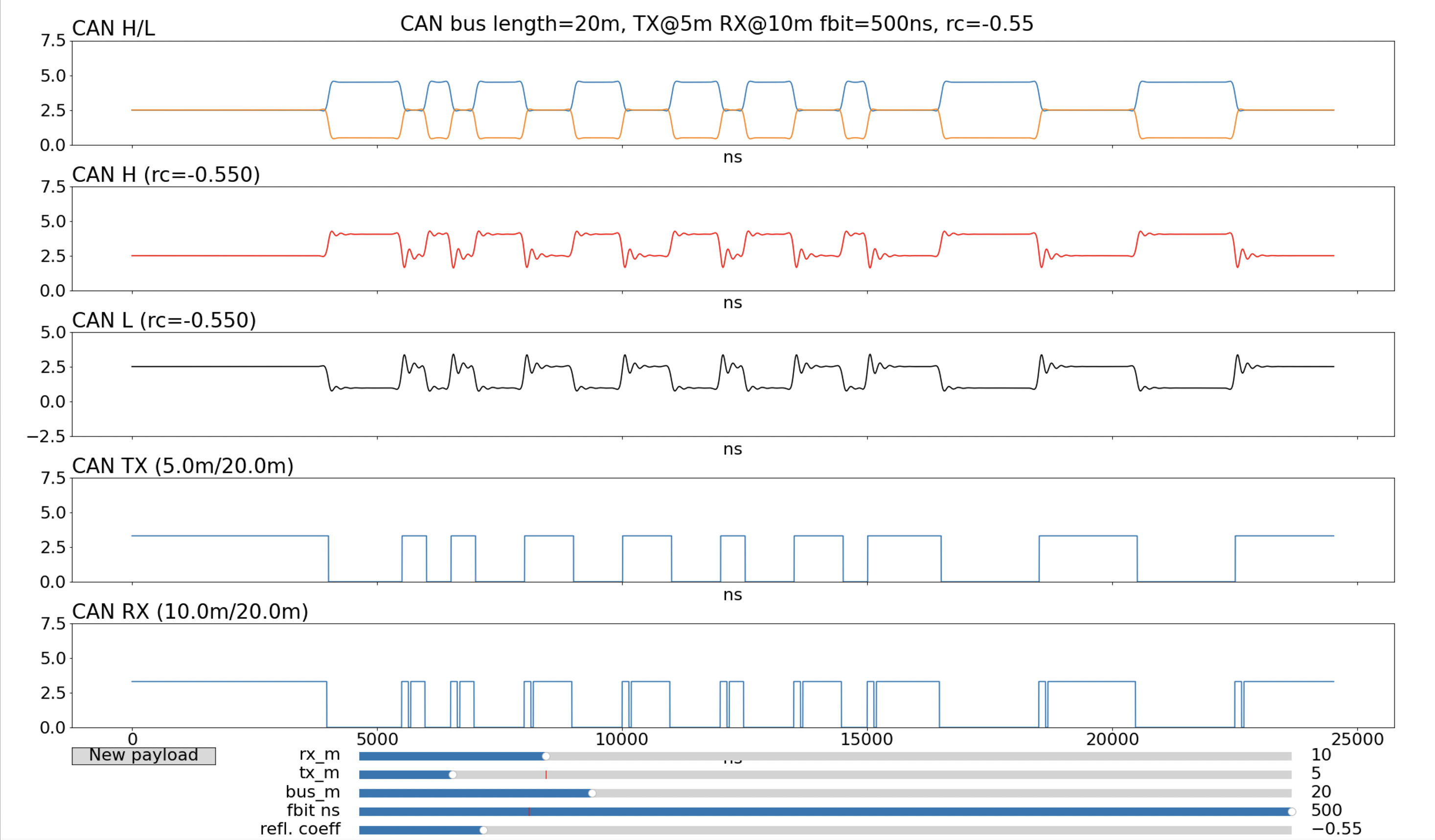
Let’s take a look at what happens if the bus has a lot of reflections due to mismatched impedance. In this example, the reflection coefficient is -0.55.
 |
|---|
| Figure 2: 20m CAN bus with a reflection coefficient of -0.55 |
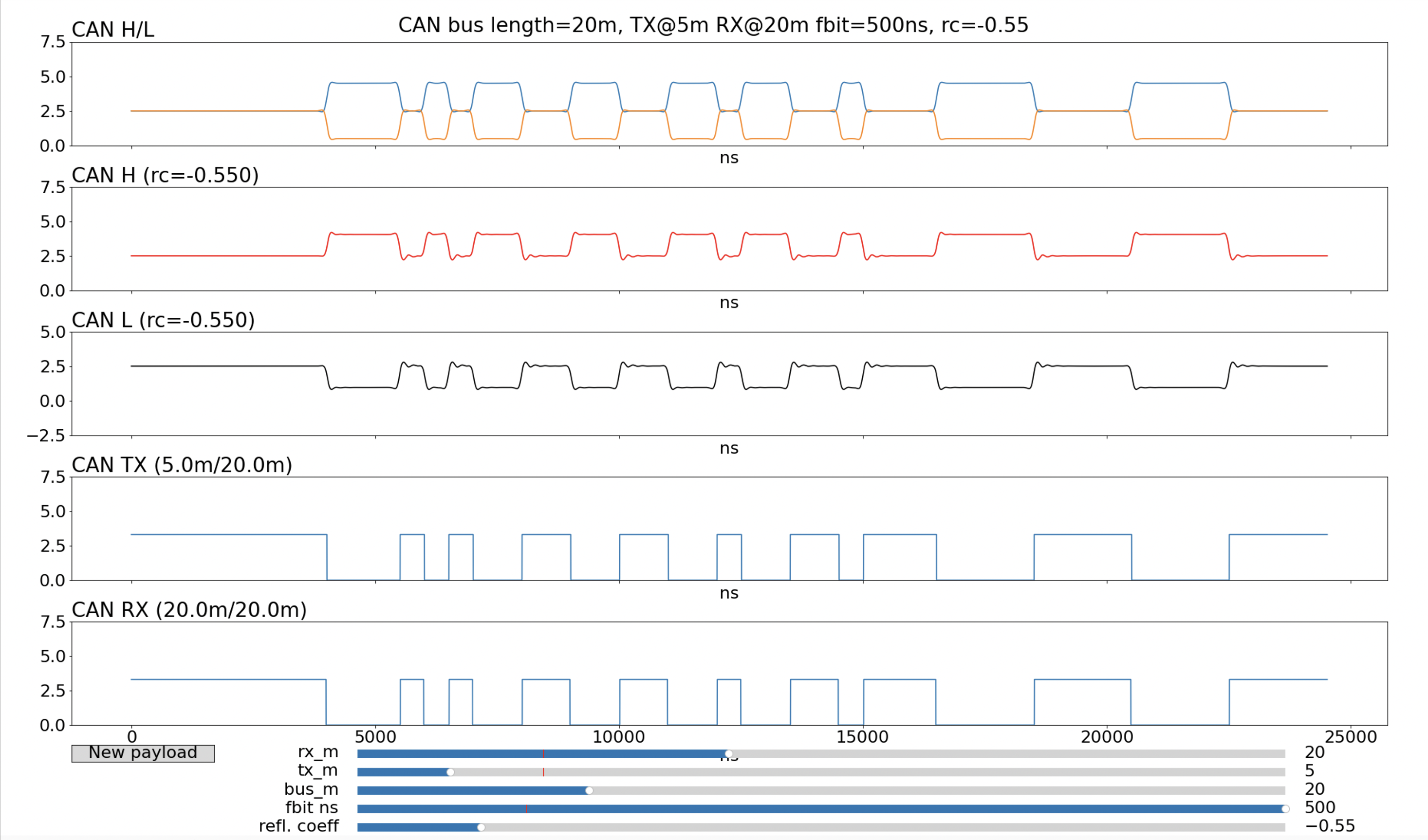
What we can see here is the classic distortion we call ringing: the reflections flip sign when they bounce of an end of the bus and so the overall sum of these waves crashing into each other is the distinctive ‘wobbling’ with a diminishing amplitude. The differential signal (CAN H minus CAN L) has little spikes due to the ringing and if the amplitude is large enough then the hysteresis of the receiving transceiver is overwhelmed and the digital state is flipped back for a short time. This shows up as glitches on the CAN RX signal. In the example above, there are glitches in the received signal. In general, these glitches can cause trouble for CAN FD because they are edges that could potentially cause the receiver to synchronise its clock to the wrong edge. Where the glitches appear and how wide they are depends on the exact placement of the receiver and transmitter on the bus. If we move the receiver to the far end of the 20m bus we see that the glitches go away:
 |
|---|
| Figure 3: 20m CAN bus with from Figure 2 with the receiver moved to the end |
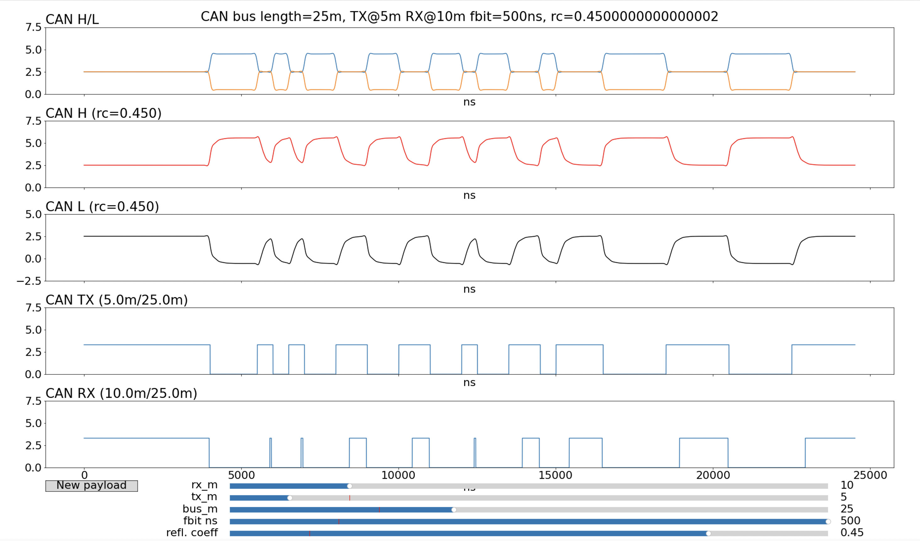
This is the problem of designing a CAN FD bus: it’s not enough to test a particular setup because small changes (lengthening the bus, or having transmitters and receivers at different places) can have different results. We can see this again by looking at a positive reflection coefficient:
 |
|---|
| Figure 4: 20m CAN bus with reflection coefficient of +0.45 |
These reflections distort the signal in a different way to glitches: in place of the ringing is a slow asymptotic rise or fall to the new voltage level. This has the effect of shortening recessive bits. In this example, a 500ns recessive bit is shortened to just 130ns. It’s still possible for a CAN FD receiver to see this bit, since even 130ns is a relatively long time compared to the sampling clock rates, but it makes selecting a sample point difficult, especially if it is to be a universal sample point that has to work for all devices no matter where on the bus and for all potential reflection coefficients.
If the bus is lengthened by just 5m and the receiver moved to 10m, the 500ns recessive pulses become very short: just 50ns.
 |
|---|
| Figure 5: CAN bus from Figure 4 lengthened to 25m and receiver moved to 10m |
If the receiver is moved just a litttle further up the bus to 7m then the single 500ns recessive bits disappear completely and no communication can occur.
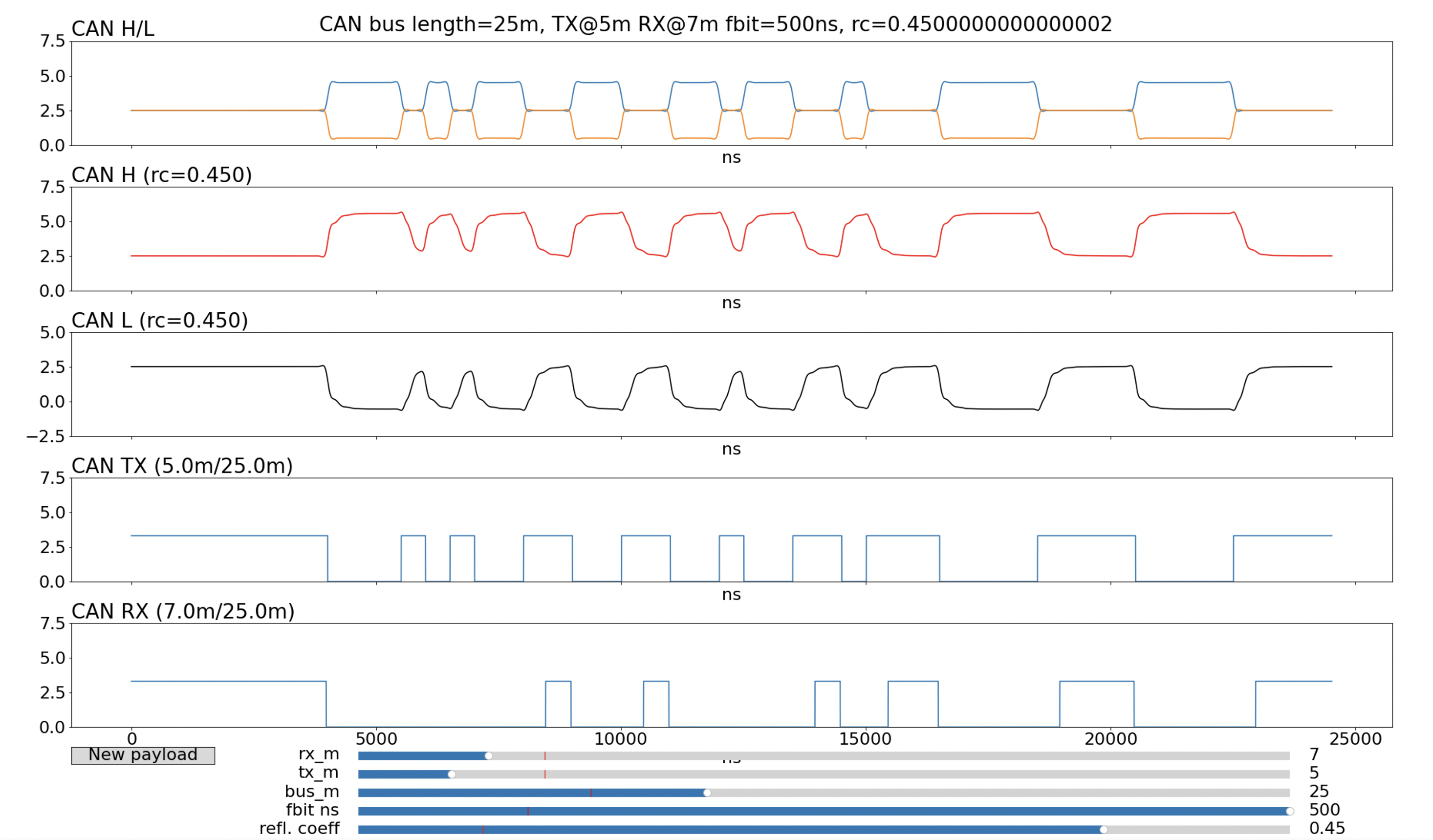 |
|---|
| Figure 6: 25m CAN bus from Figure 5 and receiver moved up by 3m |
Those first two recessive bits went missing, and this will surely result in a CAN error at the receiver (probably a CRC error).
It’s worth emphasising that this distortion of the CAN bus signals is deterministic: it is not random noise and the same pattern of transmitted data will produce the same pattern of received data. So if this distortion result in a CAN error at the receiver (as as in Figure 6) then it will always result in a CAN error and the CAN frame will be repeatedly retransmitted according the CAN protocol until either the transmitter or the receiver goes Bus-Off. In effect, the CAN bus is permanently broken.
One way to address the issue of CAN bus wiring and bit speeds is to start from existing CAN bus wiring, use a test tool to inject signals of varying patterns into the bus, collect the results (both the CAN H and CAN L analog signals and the CAN RX digital signal (ideally for different CAN transceivers) and construct a model from this data. Then the model can be used to exhaustively test all combinations of transmitter and receiver positioning so that the overall suitability of the bus can be assessed for a given bit rate.
