The CANPico board

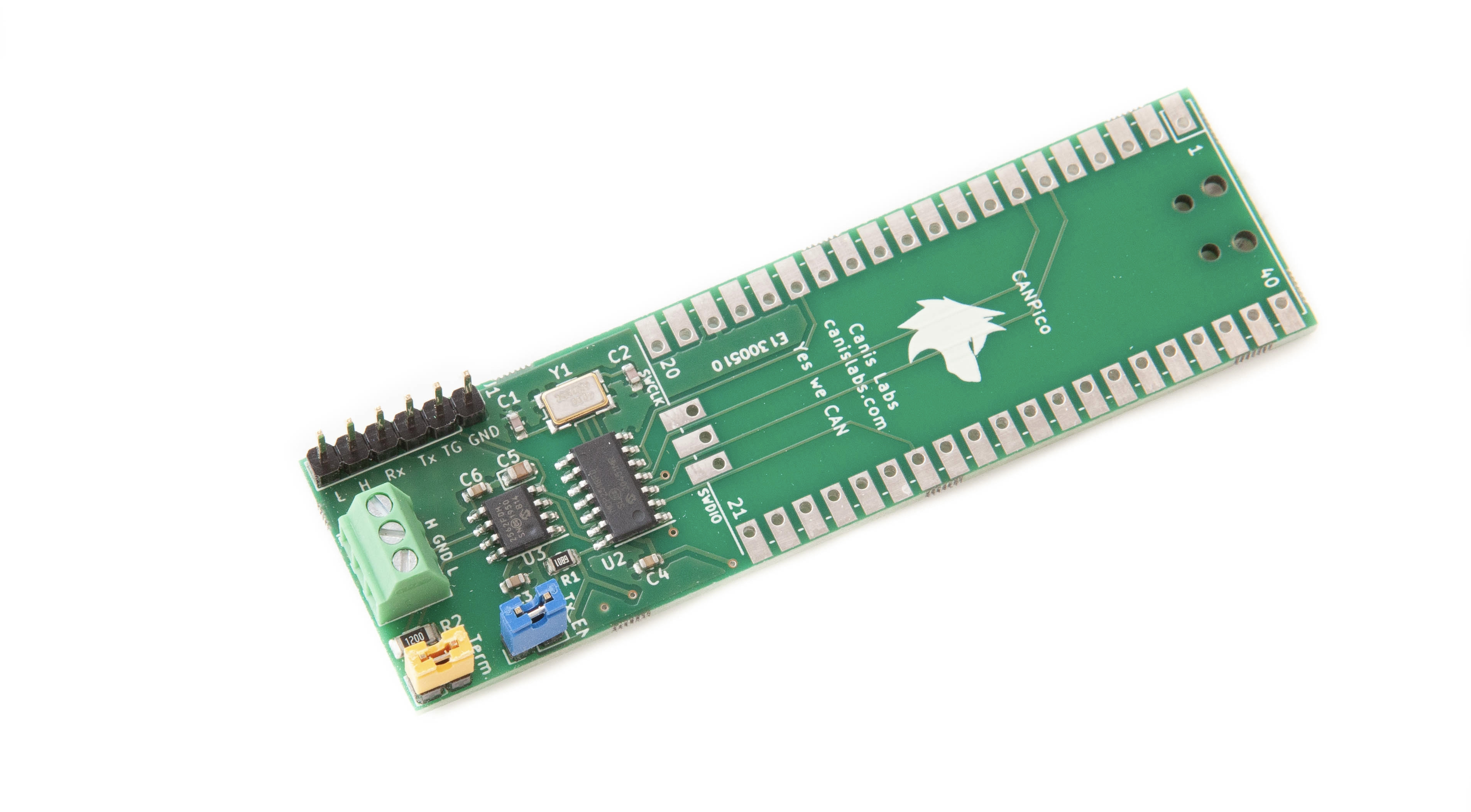
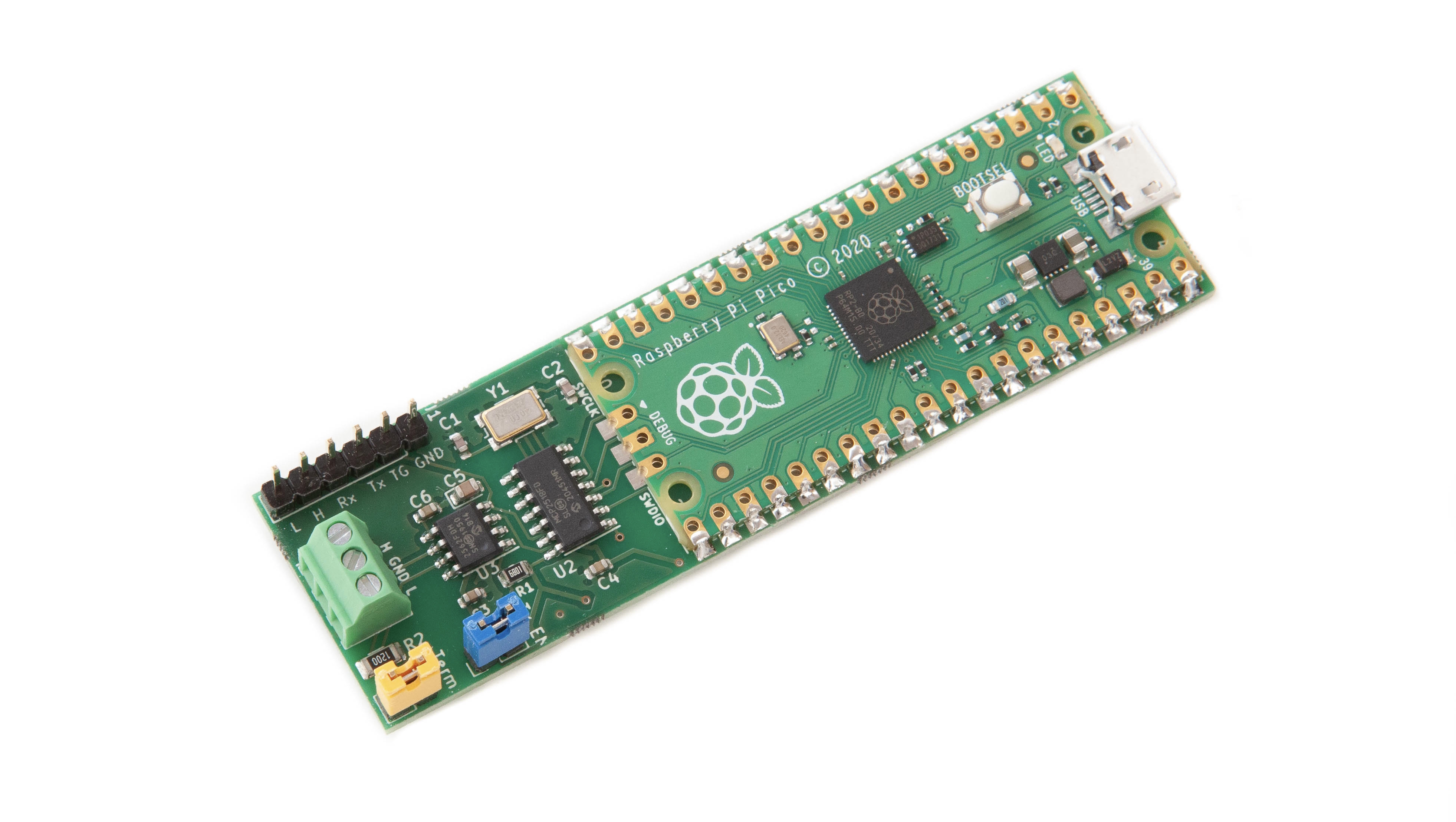
CAN bus is a protocol used in hundreds of millions of devices including cars, trucks, buses, construction machines, ships, tractors, and spacecraft (there is even a CAN bus orbiting Mars). The Canis Labs CANPico a carrier board in a ‘sock’ format for a Raspberry Pi Pico: simply solder on the Pico and it is connected to an advanced CAN controller and transceiver, ready for connection to CAN bus wires via a simple screw terminal. The CANPico includes an instrument header with the analog CAN H and CAN L signals and the digital RX and TX signals for use with an oscilloscope or logic analyzer. Software support is via an open source MicroPython SDK.
The open source MicroPython SDK from Canis Labs provides a sophisticated CAN API, including priority-inversion free drivers, 1μs accuracy timestamps, large buffers and an API for triggering a logic analyzer or oscilloscope. And there is support for communicating to a host device over USB (via the MIN protocol) to enable applications like bus logging or even using a CANPico as a PC CAN interface. The SDK also includes the CANHack toolkit for low-level error injection. The SDK lets Python code run on the dual-core RP2040 microcontroller of the Raspberry Pi Pico and respond in real-time to CAN traffic with times measured in microseconds rather than milliseconds, making it a great platform for hardware-in-the-loop test and emulation.
Main hardware features
- Microchip MCP2517/18FD CAN controller with 2Kbyte buffer space
- Microchip MCP2562FD CAN transceiver
- Screw terminal for direct access to CAN High/Low twisted pair wiring and a common ground reference
- Jumper for a standard 120Ω CAN bus termination resistor
- Jumper for enabling and disabling transmit input to the transceiver
Interfacing
- SPI interface at up to 18MHz
- Header pins for logic analyzer access to digital CAN signals (TX and RX pins of the transceiver)
- Header pins for oscilloscope access to the analog CAN signals (CAN High/Low, ground)
- TRIG pin for logic analyzer and oscilloscope triggering on programmable CAN events
- Direct GPIO access to CAN RX and TX pins for software error injection
- GPIO control over transceiver low power standby
The Raspberry Pi Pico is designed to be soldered on to a board using the ‘half moon’ edges, leaving header pins free. The other connections are USB (for power and connectivity to a host) and the CAN bus. The 6-pin header is intended for a logic analyzer and oscilloscope to see raw CAN signals, the yellow jumper is for enabling the termination resistor, and the blue jumper enables transmission on the bus (if this is removed then the board is restricted to only listening to the CAN bus, a useful security feature).

Software support
The software support is provided with a MicroPython SDK that has the following APIs:
- CAN API
- CANHack toolkit API
- Trigger API for triggering test instruments on CAN errors and CAN frames with a specified ID and payload
- MIN API to communicate with a host PC over a second virtual USB serial port
The CAN API consists of the following Python classes:
- The
CANclass provides control and status of the CAN controller - The
CANFrameclass encapsulates CAN frames, which are either created in software or by receiving them from the CAN controller hardware - The
CANErrorclass encapsulates CAN error frames, which are created receiving them from the CAN controller hardware - The
CANIDclass describes a CAN ID: every CAN frame has a CAN ID, but many frames can have the same ID - The
CANIDFilterclass describes how a CAN controller should identify and accept CAN frames based on their CAN ID
The MIN API provides MIN protocol support for reliable communication with a host PC. Some of the CAN API calls use a binary representation to allow items to be carried over MIN.
Resources
-
Buy online
The SK Pang store page for the CANPico board (sold with a Raspberry Pi Pico pre-installed)
-
Hardware Reference Manual
The Hardware Reference Manual (PDF) for the CANPico board (version 01, issue date 2021-04-29, 8 pages) including schematics.
-
MicroPython SDK Reference Manual
The MicroPython SDK Reference Manual (PDF) for the CANPico board (version 01, issue date 2021-04-29, 32 pages). Documents both the MicroPython CAN API and CANHack API.
-
MicroPython SDK firmware
The latest firmware (.uf2, release date 2021-05-10). Based on the v1.15 release of MicroPython for the Pico. The source code is released as a patch file for this MicroPython version (see README.txt for details).
-
Board design files
The latest schematics (PDF) and Kicad design (.kicad_pcb) for the CANPico board.
-
MicroPython SDK API examples
The canpico.py examples for the CANPico board (the Thonny IDE can be used to put the file on to the Pico file system)
-
Introduction to CANHack
There is a blog post introducing CANHack and a demonstration video (Note that these both use the CANHack MicroPython API but on the STM32-based PyBoard rather than the Raspberry Pi Pico).