
PulseView is a pretty neat logic analyzer, especially when paired with our can2 CAN protocol decoder and a low-cost logic analyzer. But what would be even better would be to have it run on the Raspberry Pi so that a dedicated standalone device could be used as a benchtop tool (especially with a small touchscreen). Unfortunately, the binaries for PulseView aren’t distributed by Sigrok for the Raspberry Pi. They can be built from source and this blog post shows how to do that, starting from a completely fresh install of Raspberry Pi OS.
Getting started
The microSD card for the OS should be at least 8GB. And the Raspberry Pi should have at least 4GB RAM (the compilation process takes so much memory that the OS kills the compiler if there’s just 2GB RAM). Once built, the image will work on a smaller memory board.
Installing the Raspberry Pi OS on to the card is straightforward from the official Raspberry Pi software page:
https://www.raspberrypi.org/software/
I wanted to run a headless system, so I added a file ssh
to the boot folder on the microSD card (you can’t do
this in Windows, by the way: it throws a hissy fit about
the card being unreadable).
To run it headless, just the microSD card into the Raspberry Pi,
plug in an Ethernet cable, and power it on.
It will run a ssh server and pick up an IP address. There
are lots of ways to find the IP address but I like the
iOS app Net Analyzer
on my iPhone: it’s an excellent tool for scanning networks, and
the board shows up as raspberrypi in the scan list.
I installed remote desktop using VNC from the official page here:
https://www.raspberrypi.org/documentation/remote-access/vnc/README.md
I set the Raspberry Pi to boot into desktop
automatically by using sudo raspi-config and selecting
System Options.. Boot / Auto Login.. Desktop Auto login. Don’t forget to set the screen resolution to 1920x1080
(otherwise the VNC server won’t run).
Reboot the board after quitting raspi-config.
I’m using Windows to connect to the Raspberry Pi remotely, but there are lots of other options, all covered by RealVNC:
https://www.realvnc.com/en/connect/download/viewer/
Use the IP address found earlier to log in via VNC. The desktop will be tiny, so set it to use that full HD resolution of 1920x1080 (RPi menu.. Preferences.. Screen Configuration, and don’t forget to apply the choice).
OK, that’s a vanilla install of a Raspberry Pi with a remote desktop.
Installing packages
First step, update the OS packages to their latest versions:
1
2
$ sudo apt-get update
$ sudo apt-get upgrade
PulseView requires Boost, which needs to be installed:
1
$ sudo apt-get install libboost-all-dev
And there are a lot of other packages that are needed:
1
2
3
4
5
6
$ sudo apt-get -y install gcc g++ libtool automake autoconf libftdi-dev libusb-1.0-0-dev libglib2.0-dev check
$ sudo apt-get -y install libzip-dev libglibmm-2.4-dev doxygen python3.4-dev python-gobject-2-dev swig3.0
$ sudo apt-get -y install qtbase5-dev qtbase5-dev-tools libqt5svg5-dev libevent-pthreads-2.0-5 cmake
$ sudo apt-get -y install libboost1.58-dev libboost-filesystem1.58-dev libboost-system1.58-dev libboost-serialization1.58-dev
$ sudo apt-get -y install qt5-default qttools5-dev libqt5svg5-dev
$ sudo apt-get -y install sigrok-firmware-fx2lafw
We also want to be able to access the USB serial ports:
1
$ sudo gpasswd --add $USER dialout
Now we can get the Sigrok software.
Creating the repositories
We need five repositories, and we’ll put them in a new directory github:
1
2
3
4
5
6
7
$ mkdir github
$ cd github
$ git clone https://github.com/sigrokproject/libsigrok.git
$ git clone https://github.com/sigrokproject/libsigrokdecode.git
$ git clone https://github.com/sigrokproject/sigrok-cli.git
$ git clone https://github.com/sigrokproject/pulseview.git
$ git clone https://github.com/kentindell/canhack.git
Now the messy part: building the Sigrok software.
Building libsigrok
The head of libsigrok is currently broken, so
checkout a specific point in the tree (5bf642db) that works and build
as follows:
1
2
3
4
5
6
$ cd libsigrok
$ git checkout 5bf642db
$ ./autogen.sh
$ PGK_CONFIG_PATH=/usr/lib/pkgconfig ./configure --prefix=/usr
$ LD_RUN_PATH=/usr/lib make
$ sudo PYTHONPATH=/usr/lib/python3/site-packages make install
To allow access to USB to communicate with the logic analyzer
we need to set the udev rules:
1
2
$ cd contrib
$ sudo cp *.rules /etc/udev/rules.d/
Reboot the board to get the udev rules to apply (it’s possible to
get them to apply without a reboot but it’s too complex and life
is too short). Log back in again.
Installing the Sigrok protocol decoders
The decoders are in Python and they are installed as follows:
1
2
3
4
5
6
7
$ cd github
$ cd libsigrokdecode
$ ./autogen.sh
$ ./configure --prefix=/usr
$ LD_RUN_PATH=/usr/lib make
$ sudo make install
$ cd ..
Add in our can2 CAN protocol decoder:
1
2
3
$ cd canhack
$ sudo cp -r can2 /usr/share/libsigrokdecode/decoders/
$ cd ..
Sigrok commandline tool
The command line version of Sigrok is useful for testing the install has worked:
1
2
3
4
5
6
$ cd sigrok-cli
$ ./autogen.sh
$ PKG_CONFIG_PATH=/usr/lib/pkgconfig ./configure --prefix=/usr
$ LD_RUN_PATH=/usr/lib make
$ sudo make install
$ cd ..
We can quickly check all the drivers are installed and everything is working by plugging in a logic analyzer and running:
1
2
3
4
$ sigrok-cli --scan
The following devices were found:
demo - Demo device with 13 channels: D0 D1 D2 D3 D4 D5 D6 D7 A0 A1 A2 A3 A4
fx2lafw:conn=1.5 - Saleae Logic [S/N: Saleae Logic] with 8 channels: D0 D1 D2 D3 D4 D5 D6 D7
If there are errors to do with USB then probably the udev rules
weren’t applied (or the board wasn’t rebooted after). If there are
errors about firmware then probably the sigrok-firmware-fx2lafw
firmware package wasn’t installed.
Building and installing PulseView
Remember, PulseView won’t build on a Pi with only 2GB RAM because
one of the files is too complex and the build fails with the compiler being terminated (the status of RAM available
can be checked with the commandline tool htop).
1
$ cd pulseview
Firstly, the file CMakeLists.txt needs to be edited to
explicitly link libatomic (it’s supposed to be automatic but this doesn’t
seem to work). Edit the file and explicitly set -latomic by
going to this place in the file and changing that last line:
1
2
3
4
5
6
set(PULSEVIEW_LINK_LIBS
        ${Boost_LIBRARIES}
        ${QT_LIBRARIES}
        ${CMAKE_THREAD_LIBS_INIT}
        -latomic
)
Then create a build directory and build PulseView:
1
2
3
4
5
6
$ mkdir -p build
$ cd build
$ PKG_CONFIG_PATH=/usr/lib/pkgconfig cmake -DCMAKE_INSTALL_PREFIX:PATH=/usr -DCMAKE_INSTALL_RPATH_USE_LINK_PATH=true -DDISABLE_WERROR=1 -DENABLE_TESTS=n ..
$ make -j4
$ sudo make install
$ cd ..
The -j4 tells make to use all four cores of the Raspberry Pi,
which will speed things up considerably.
When that’s built and installed, it can be run from the commandline:
1
2
3
4
$ pulseview
qt5ct: using qt5ct plugin
palette support is disabled
libpng warning: iCCP: known incorrect sRGB profile
The PulseView window will open and it can be driven in the normal way.
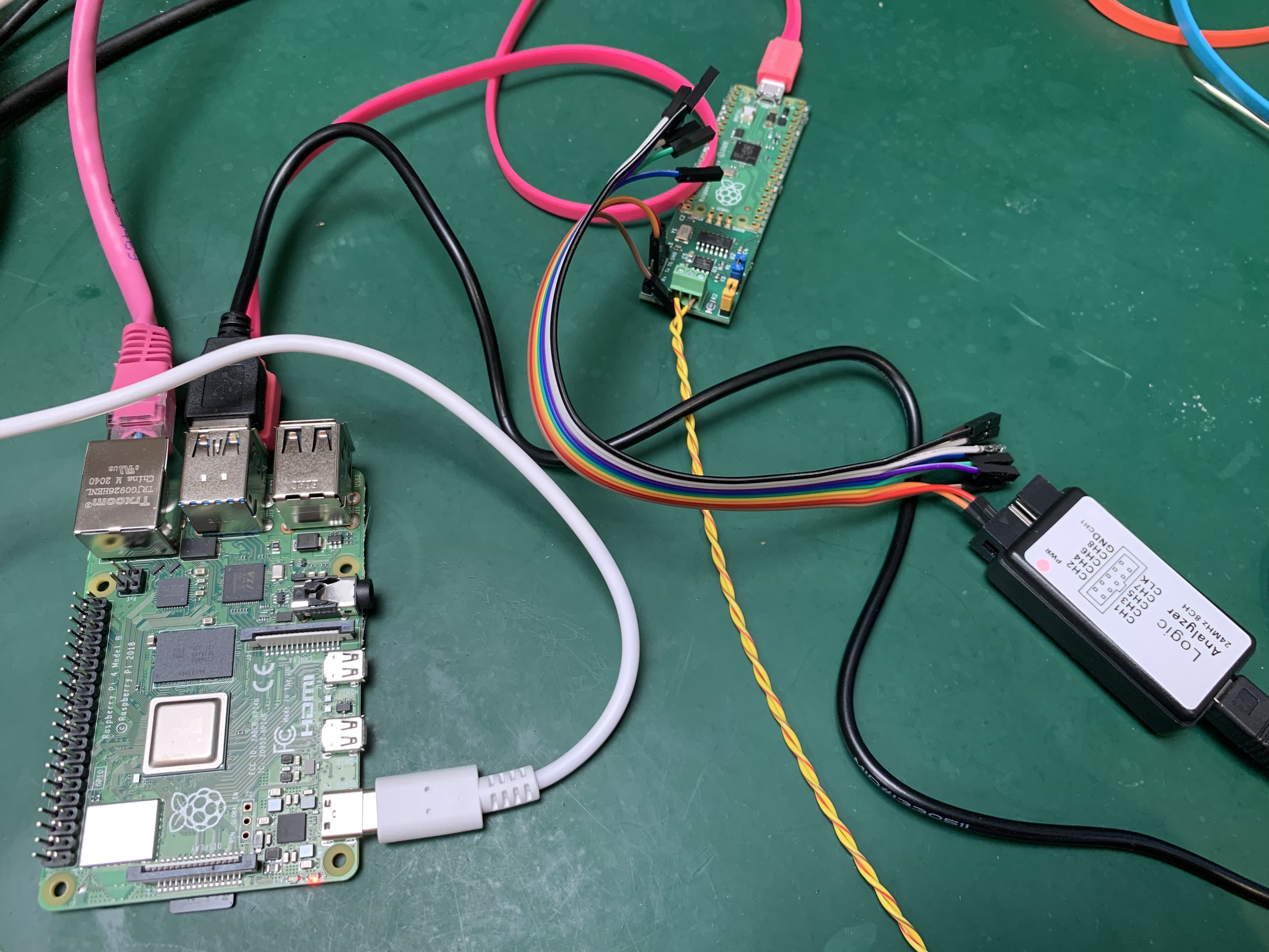
The above build was done on a Raspberry Pi 400 (with 4GB RAM), then it was shut down the microSD card moved to a Raspberry Pi 4 with 2GB RAM. Here it’s on a benchtop, connected to a low-cost logic analyzer, an official Raspberry Pi USB C power supply, a Canis Labs CANPico board (available for order online from SK Pang) and Ethernet.
Two inputs of the logic analyzer are connected to the CAN RX and CAN TX pins of the transceiver via the CANPico instrument header. The CANPico is connected to a CAN bus but there are no other devices on the bus.
The screenshot below shows a CAN frame sent from the CANPico, with PulseView on the Raspberry Pi decoding the CAN bus.
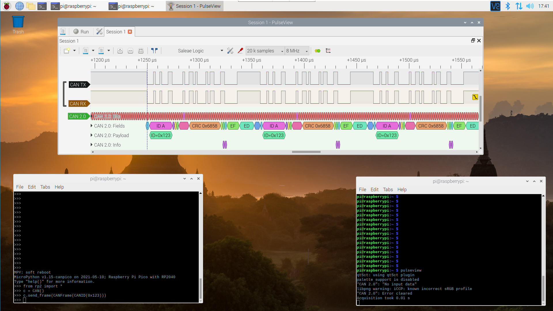
The CAN frame is sent repeatedly because there are no other devices on the CAN bus, an interesting quirk of the CAN protocol that will be the subject of an upcoming blog post.
