
We said in our previous blog post that “Our next goal is to create a GTKWave filter so that an arbitrary waveform can be decoded” and in an early Christmas present to those who are into the CAN protocol, we’ve done that! But we’ve done even better and we therefore present to you the new CAN protocol decoder for the Sigrok project.
First, a quick summary of Sigrok:
it’s a set of drivers and tools that
provide a desktop oscilloscope / logic analyzer UI for many, many different
instruments (from Siglent, Rigol and others). The UI runs on
Mac, Windows and Linux (and others) and the GUI is called PulseView (there’s
also a command-line tool for batch decoding, useful for an automated test
environment).
PulseView has an API for protocol decoders, and we’ve developed one for CAN: it’s called can2.
A couple of quick bear trap warnings for using PulseView before we
talk about can2:
- Don’t use the Sigrok package that comes with your Linux distro: it’s very likely to be too old and there have been lots of changes; download binaries directly.
- If importing a VCD file make sure the Downsampling factor is set so that the logic analyzer sample period is no more than about 1ns. If you don’t and you feed it a VCD that came from a simulator that used 1ps steps then your PC is going to spinning up its fans for a long time!
OK, back to the protocol decoder it can be installed by
copying the directory can2 (containing two Python files) into
the directory (on Linux) ~/.local/share/libsigrokdecode/decoders.
The decoder appears in the decoders list as “CAN 2.0” and it requires just one input: the CAN RX line (from the RX pin of a CAN transceiver). The options include the sampling point (default 75%) and the bit rate (default 500kbit/sec).
When the decoder is applied to a CAN signal on it then then the output is like this:
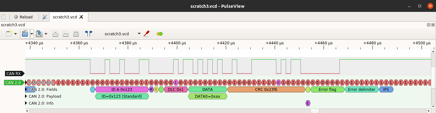
The top row of the decoder output (“CAN 2.0: Bits”) shows the CAN bits (regular and stuff bits). A tooltip will appear giving the bit value if the mouse pointer is hovered over the bit (PulseView automatically displays the information it can in the space available at a given zoom level).
The next row shows the CAN fields: the first bit is SOF (Start of Frame), the next is the 11-bit ID, and so on. A frame ends with the IFS field. Two other states are not shown: Bus Integration (where the decoder is syncing to the CAN signal from a reset state) and Idle (where nothing is happening).
The third row shows the full CAN ID (if the frame is an extended frame - i.e. IDE=1 - then there is a second 18-bit field, and the ID is then 29 bits long). The row also shows the payload decoded into individual bytes.
The fourth row is the really interesting one: it shows information about the CAN frame. In the screenshot, it displays an “E” to indicate an error flag. The tooltip says “Form error”, which means that the field contains the wrong value: it is read as a dominant (0) bit and it should be recessive (1). This is an indication of an error, and the decoder shows that the subsequent bits are an Error Flag followed by an Error Delimiter, and then IFS again.
The info row also shows other interesting events, including:
- When the frame has been received OK (i.e. second to last bit of EOF)
- When the frame has been transmitted OK (i.e. last bit of EOF)
- If there is an ACK error (i.e. the ACK bit is not 0)
- If the received CRC doesn’t match the calculated CRC (the protocol decoder keeps track of the expected CRC value)
- If there is a ‘double receive’ (i.e. there is an error after the frame has been received OK but before the frame has been transmitted OK)
- If there is an overload rather than an error. Modern CAN controllers should never generate overload frames so to see one means that something odd is going on. To see two in a row means something very odd is going on.
The last two are symptoms of protocol attacks: the Double Receive Attack
and the Freeze Doom Loop Attack.
The CANHack toolkit can actually
generate these attacks (and a whole bunch of other attacks)
and so the can2 protocol decoder is a good starting
point if an attack on the CAN bus is suspected.
The CAN Double Receive problem isn’t just a symptom of an attack: it can happen for real, and is a consequence of CAN’s amazingly useful atomic broadcast property (very few communications protocols provide this and it’s an essential building block for robust mission-critical applications). So a top tip for anyone building a CAN-based application: for any frame that includes event-based data (like a command) then include a sequence number (it can be just one bit) so that duplicates can be detected and discarded. Doing this doesn’t just fix a wrinkle in the protocol, it also defends against the Double Receive Attack.
Finally, a couple of things about the decoder. It doesn’t implement the
CAN time quanta bit sampling scheme (where sync is limited by the SJW
parameter) but it does implement the sync rules (in particular, glitches after
a bit is sampled as 0 are ignored). Also, can2 goes into
Bus Integration if it samples the CAN r0 bit as recessive, which means that
CAN FD frames are ignored and skipped over rather than causing the decoder
to get scrambled (incidentally, this is why CAN FD can’t share a bus with
classic CAN 2.0 controllers).
Oh, one last thing: anyone wanting a GTKWave filter for CAN could use this
neat little tool to turn the can2 Sigrok decoder into exactly that.
