
The question: There is a CAN node that’s acting very strangely on a 500kbit/sec CAN bus. What is happening?
The specific timings are very important clues. A single burst of pulses consists of:
- A dominant pulse of 34 microseconds
- Followed by 15 cycles of 50 microseconds recessive / 2 microseconds dominant
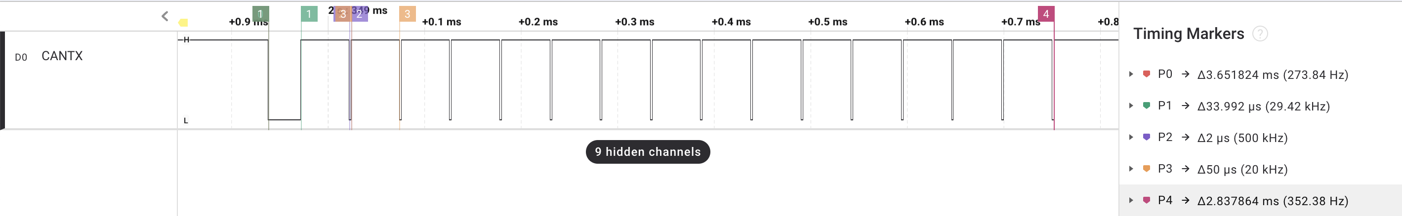
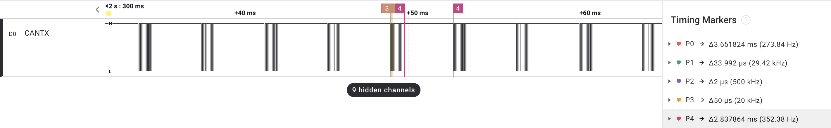
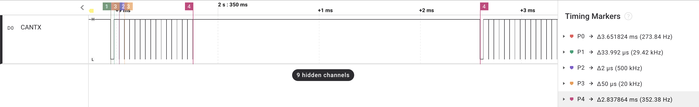
The time between the end of the last 2 microsecond dominant pulse in a burst and the start of the 34 microsecond dominant pulse of the next cycle is 2.837864 milliseconds.
The Answer
The Fault
The CAN controller is initially sending an SOF (Start-Of-Frame) bit, which puts a dominant state (logic 0) to the CAN TX pin. But there is a fault: the RX pin reads back 1 (a broken connection between the transceiver and controller, or some kind of stuck-at fault). This causes a bit error, but not just any bit error: a 0-to-1 bit error, which always results in an error frame. The CAN controller increments its transmit error counter (TEC) to 8 and starts to signal the error by sending an active error flag (i.e. six dominant bits). But the stuck-at fault means that the first bit of this error flag is also a 0-to-1 bit error. So TEC goes up by 8 again and the process repeats. After 16 times trying to signal an error with dominant bits (total of 17 bit times when including the SOF, giving a dominant bit time of 34 microseconds at a bit rate of 500kbit/sec) the TEC hits 128.
A TEC of between 128 and 255 puts the CAN controller into the transmit error passive state, which means errors are signalled by a passive error flag (i.e. recessive bits).
Error Passive
Error passive signalling is a different process to error active signalling: with error passive, the controller sends a passive error flag six recessive bits until it sees six bits of the same sign. With a stuck-at fault setting CAN RX=1, this happens straight after those six bits. The controller then sends the Error Delimiter (another 8 recessive bits). For an error passive controller that was transmitting (or trying to transmit) the previous frame, the interframe space that comes after the Error Delimiter is not the normal 3 bit times, but also includes a transmitter delay of another 8 bit times (see Figure 9 of the ISO 11898-1:2015 CAN specification). This gives a total of 6 + 8 + 3 + 8 = 25 recessive bits, or 50 microseconds of recesive at a bit rate of 500kbit/sec.
The controller then sends an SOF bit and again encounters an error because of the stuck-at fault. Again, TEC is increased by 8 (from 128 to 136) and the process repeats, with TEC increasing until it hits 256. At this point, the CAN controller goes Bus Off (i.e. takes itself offline).
Bus Off
The spirit of the CAN standard requires that the host request the recovery from Bus Off but some CAN controllers will do this automatically. While not illegal, it’s something that they shouldn’t really do (there is more discussion of this below). The trace shows 2.837864 milliseconds from the end of the SOF that puts the controller into Bus Off to the first SOF. 2.837864 milliseconds is 2837864 microseconds, or 1419 bit times at 500kbit/sec.
The process of recovery requires seeing 11 recessive bits in a row 128 times (each CAN frame - including error frames - ends with 11 recessive bits so for a 100% loaded bus this becomes a frame counter). For a stuck-at-recesive bus, this is 11 x 128 bit times = 1408 bit times. Once the controller has recovered from Bus Off it goes into a state called bus integration, which means waiting for 11 recessive bits, to sync with the bus (when a controller is started up from power-on reset it does the same: this prevents a controller trying to transmit a frame in the middle of one that’s already being transmitted on the bus, since 11 recessive bits never happens in a valid CAN frame, only at the end). The bus integration time for a stuck-at recessive bus is 11 bit times, and so the controller has been offline for 1408 + 11 = 1419 bit times (which is the observed delay on the logic analyzer trace).
So the short answer to the question is:
“A stuck-at fault on the receive causes the controller to go into an error loop, first error active, then error passive, ending in Bus Off, and then recovering automatically, and trying again - with this repeating forever”.
Supplemental questions
What could be causing this scenario to happen?
There is a hardware fault of some kind. RX is stuck at 1. This can be because of a hardware connection between the transceiver RX and the CAN controller RX pin was broken and RX floated high, or it could be because the bus was idle but the connection from the controller TX to the transceiver TX was broken (the transceiver will float high if the TX pin is not driven).
What could be the consequences?
If TX connection is broken then the consequences are confined to the transmitting node: frames will get stuck in the controller and never be sent. Depending on the CAN controller hardware, the node may receive frames from the bus (the ISO 11898 specification does not prohibit receiving frames during Bus Off). Or the CAN bus may appear to go silent and various heartbeat messages not be received.
If the TX connection is not broken and the RX is stuck at 1 then the consequences for the bus could be dire: the signal in the trace will be overlaid on to the bus, causing many frame failures. The periodicity of the bursts is 3.65ms, of which 2.84ms is in Bus Off. In other words, for nearly 22% of the time, the node is disrupting CAN bus communication. For a bus that is running with a high utilisation and hard real-time communications requirements on CAN frames, that is seriously disruptive. It could cause a lot of consequential failures at other nodes.
How could the situation be detected?
The node can detect the problem from type of errors: it’s a 0-to-1 bit error. Normally this should be very rare and maybe never seen. But the trace above will show it to be very common. Some controllers will report the error type, and some will report which type of bit error (1-to-0 vs. 0-to-1) is seen.
The situation can also be detected by software keeping track of the number of times the controller goes Bus Off. For controllers that automatically recover this is less straightforward than for controllers that are explicitly instructed to recover, usually requiring a “Gone bus off” event to be detected (typically by an interrupt service routine). If the node experiences a fault soon after recovering from bus off then this fault has occurred.
How could it be mitigated?
The most important thing to do is to not allow automatic Bus Off recovery and instead operate a network management policy that explicitly requests recovery, with a permaent disconnect if recovery fails (or at least a long delay between recovery attempts, long enough not to disrupt the bus too much). The way to do this with CAN controller hardware that automatically recovers is to handle the interrupt indicating a Bus Off event and then forcibly put the controller into an offline state and then later do a clean recovery.
Super-Expert Level Supplemental Question
Which CAN controller is this?
This is the MCP2515. While it is not unique in recovering automatically from Bus Off, it has a particular design failing: the transmit buffers are not flushed when going into Bus Off. So it will, unless specifically prevented by software, immediately try to re-send whatever is in its transmit buffer and, with this stuck-at fault, do so in a short period loop forever.
