
We have written before about priority inversion, how it happened on Mars, and how it happens on CAN bus if the CAN controller and drivers aren’t designed carefully. But we have been bitten by priority inversion while writing code for the new Raspberry Pi Pico so we are writing about it again - because the consequences can be just as severe as they were on Mars.
First, some background to the Pico. It’s a $4 microcontroller board from the Raspberry Pi Foundation that uses a new microcontroller they designed from scratch: the RP2040. This is a dual core Arm Cortex M0+ device that has several unusual features. It runs the Cortex M0 very quickly (defaults to 125MHz), it has two cores, and it doesn’t have any flash memory. This last feature is rapidly becoming a trend in microcontrollers: flash memory is slow and even on slow Cortex M0 cores running at 48MHz it generally can’t keep up (the Atmel SAMD series, for example, runs code from flash with wait states). A recent approach is ‘XIP’ - eXecute In Place - where the code is stored externally in a serial SPI flash (QSPI - quad SPI - on the RP2040) with a big cache so that the code runs reasonably quickly. One way to look at this system is to think of it as like virtual memory in mainstream computers: a cache miss is like a page fault, where the OS (or in this case the hardware) goes off to a disk to load the page. Things can run quite well in most cases if the paging algorithm (i.e. cache design) is good.
While average performance might be OK, for time critical functions it’s terrible: the code at the start of an interrupt handler will almost always cause a cache miss, which means that the CPU will be frozen while the interrupt service routine (ISR) code is loaded from external SPI. This can potentially take dozens of microseconds (or the equivalent of thousands of CPU instructions) - way too long for an ISR that’s part of a device driver servicing an external piece of hardware. The solution to this on the Pico is to put time critical functions into RAM. The Pico C SDK supports this by marking C functions as time critical, which are then copied from flash to RAM at startup (with the linker taking care of mapping all the addresses properly). For example, this will put the handler for our MCP2518 CAN controller into RAM:
1
void __attribute__((noinline, long_call, section(".time_critical"))) mcp2518_irq_handler(void);
This isn’t enough, though, because the vector table must also be in RAM - otherwise the CPU will stall when fetching
the vector for the IRQ. On the RP2040 that’s done by setting the Cortex M0 register VTOR to point to a table in RAM (again,
taken care of by the linker and startup code).
Unfortunately, this still isn’t enough - because of priority inversion.
It’s very common in a real-time system for code that runs in background (perhaps not even real-time code) to share data with an ISR (e.g. if the ISR is part of a driver for a communications controller and putting data into a FIFO, with the background code reading data from the FIFO). If the background code is in the middle of updating a shared data structure (e.g. moving the head of a FIFO along) and the ISR interrupts it then the data structure can be corrupted. The section of background code that accesses the shared data structure is known as a critical section and must be run atomically (i.e. if it starts then it must complete before anything else accesses the data structure). The normal way to implement a critical section is to disable interrupts (either a specific source of interrupts or all interrupts). When the code is running, the interrupt will be delayed. This normally works OK: critical sections are short (in the case of a FIFO, just long enough to flip a couple of pointers). In the MicroPython firmware, there are a couple of macros defined so that target-independent code can enter a critical section. Here’s an example for a Bluetooth stack:
1
2
3
4
5
6
// This is used to protect the ringbuffer.
// A port may no-op this if MICROPY_PY_BLUETOOTH_USE_SYNC_EVENTS is enabled.
#ifndef MICROPY_PY_BLUETOOTH_ENTER
#define MICROPY_PY_BLUETOOTH_ENTER mp_uint_t atomic_state = MICROPY_BEGIN_ATOMIC_SECTION();
#define MICROPY_PY_BLUETOOTH_EXIT MICROPY_END_ATOMIC_SECTION(atomic_state);
#endif
On the RP2040 port of MicroPython, the
macro MICROPY_BEGIN_ATOMIC_SECTION maps to a cpsid instruction that disables
all interrupts. This is a quick way of ensuring atomic access to a datastructure because the instruction executes very
quickly on an Arm Cortex M CPU. Unfortunately, on the RP2040 code can cause a cache miss at any point and then lock the CPU
for a great chunk of time. Which is what happens on the MicroPython port. Here’s the code for one of the functions that
executes in background:
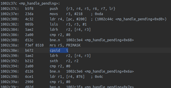
The code after that cpsid instruction is running in XIP memory (on the RP2040 that begins at 0x10000000). As soon as a
cache miss occurs, a high priority interrupt will be held out for a chunk of time. Here’s our ISR for the Microchip MCP2518
CAN controller drivers:
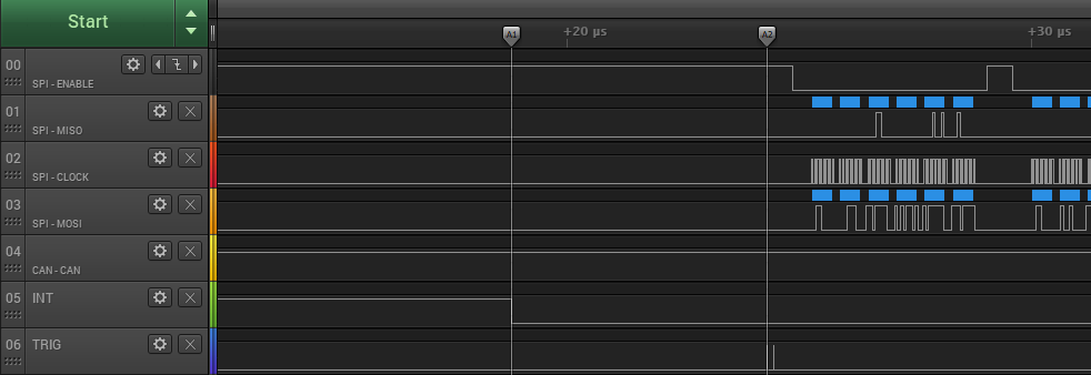
The interrupt line INT is the active low interrupt pin on the MCP2518. It goes low when the CAN frame has been sent. The TRIG line is a trigger pin used here to measure time: it’s set high then low as the first instructions of the ISR (put into RAM to make sure it runs fast without any cache misses). The time between the INT line going low and the start of the ISR is a whopping 10 microseconds! The low priority background task is stalling the urgent ISR because it’s delayed by the medium priority activity of fetching code and data from serial flash - a classic example of priority inversion.
There are a couple of solutions to the specific MicroPython problem described above. One is to make all the critical sections
into functions that are located in RAM, so there can’t be a cache miss. But it’s very easy to make a mistake: a single access
to the flash memory could cause that stall (not just execution, but even accessing any data item, directly or indirectly,
that’s declared const in C).
The other approach is to take advantage of the Arm Cortex M0 NVIC and use interrupt priority levels. The NVIC is a bolt-on logic block that gives each interrupt a priority level, so that one interrupt can interrupt another of lower priority. On the Cortex M0 there are four levels of interrupt priority. So instead of disabling all interrupts, it’s possible to disable to a ‘ceiling’ level: the highest priority of ISRs that share data with MicroPython. Urgent ISRs that don’t have shared access have priorities higher than this ceiling and will run without being delayed, even if the background code is running slow due to cache misses. In fact, this is an example of the general solution to solve priority inversion: the Priority Ceiling Protocol.
The Priority Ceiling Protocol is often adopted in real-time operating system (RTOS) design. For example, the automotive
industry AUTOSAR Run-time Environment (RTE)
includes the concept of
‘resources’, and defines a pair of API calls (GetResource and ReleaseResource) that cause the calling task’s priority
to be boosted to the ceiling priority of the resource, where the ceiling is the priority of the highest priority task that’s
defined to access the resource.
In many ways, interrupt handlers are like RTOS tasks implemented in hardware. It’s even possible to directly implement some of the more sophisticated RTOS API functions directly in hardware on top of interrupt logic. This is the approach we took in designing a new CPU architecture for automotive domain controllers.
The problem of priority inversion is very widespread and it pops up all over Earth as well as Mars. But the solutions to it open up some very interesting aspects of real-time systems design.
