Three new CAN protocol hacks
The CANHack toolkit includes support for various kinds of
attacks on the CAN protocol, including three new unpublished
attacks. These new hacks are described in this blog post. There is also
a CANHack toolkit demo video showing these attacks taking place in a
hardware rig.
The attacks are:
- The Double Receive Attack. This is where a transmitter’s CAN controller is made to re-send a frame so that other CAN controllers receive it multiple times.
- The Freeze Doom Loop Attack. This is where the CAN bus can be silently frozen after a frame is sent, and held in that state for an arbitrary time by the attacker.
- The Janus Frame Attack. This is where bit glitching is used to attack the very lowest parts of the CAN protocol to send a single frame with different contents to different receivers.
These three attacks came out of the development of a CAN hardware security solution: when working on a Blue Team project the best approach is to wear a Red Team hat and think like a hacker. That development led not only to the attacks but also hardware mitigations for them (we will talk about these in a future blog post).
Double Receive Attack
This attack exploits a feature/corner case of the CAN protocol where a receiver and a transmitter handle the end of frame differently.
In the ISO 11898 CAN protocol specification, a receiver that sees the EOF1 bit (i.e. the second-to-last bit of the EOF field) as a recessive bit treats the frame as received OK. The transmitter needs to see the last bit of the EOF field (EOF0) as recessive for the frame to count as sent. If there is an error in EOF0 then the transmitter will not mark the frame as sent, and will re-enter it into arbitration. When it later is sent, the receivers will see it again. From the perspective of a transmitter, the frame is sent once. From the perspective of receivers, the frame is received more than once.
This is a part of the CAN protocol, but it is also inherent to the behaviour of the real world: it is simply impossible to obtain consensus on sent/received with a fixed latency (this is known as Buridan’s Principle). The CAN standard specifically highlights the issue, which can be resolved in software with a sequence number in the payload but the problem isn’t widely known and so this often isn’t done.
The CANHack toolkit specifically targets the EOF0 bit to force a double receive.
The MicroPython call looks like this:
1
2
>>> ch.set_frame(0x123, data=bytes([0x01]))
>>> ch.double_receive_attack(repeat=1)
The logic analyzer trace looks like this:

It shows how the CANHack software injects an error frame on to the CAN TX pin
precisely at the start of the EOF0 bit, and this causes the double receive.
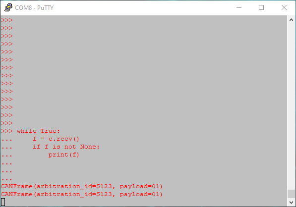
We often use a PyBoard as a simple bus analyzer with a while loop displaying
frames received. This shows two frames received even though the
transmitting CAN controller was loaded with just one:
This hack could be used as part of an overall attack on a system. It could be used to defeat a simple software security approach where each device receives all CAN frames to check for spoofing: the double receive attack causes the legitimate sender to send the frame twice, so defeats such simple defenses.
Freeze Doom Loop Attack
The CAN protocol contains a fossilized relic of the past: overload frames. These were originally conceived to allow slow hardware to signal it needed more time to deal with a frame (such as copying it to a buffer). It could signal an overload condition, which is basically the same as an error except that no CAN error counters are incremented (and no controller goes error passive or bus-off). It is basically flow control for CAN.
No modern CAN controller generates overload frames, but all
controllers have to handle them as part of the CAN protocol. The CANHack toolkit exploits
this by generating an overload frame (by forcing a dominant bit into the first
Inter-Frame Space bit, IFS2). This causes all CAN controllers to go through
overload recovery, with an Overload Delimiter and then the IFS field. By
again injecting an dominant bit into IFS2 the process can be repeated. While
this looping is happening the CAN bus is effectively frozen: no errors are
reported, but no frames are received or sent.
The CANHack toolkit supports this attack directly:
1
2
>>> ch.set_frame(0x123)
>>> ch.freeze_doom_loop_attack(repeat=10)
This is the trace produced by the logic analyzer:

The frame has been received OK at the start of the process; it is just arbitration that has been delayed by the attack. We can see this by sending two frames back to back (a frame with ID 0x123 and a frame with ID 0x012), with the attack targeting the frame sent first on the bus, 0x123:

This attack is quite difficult to detect by an IDS: there are no errors so the error counters don’t increment, and there is no outward sign at the frame level that this is happening: frames are sent and then they arrive some time later. With CAN, frames do get delayed by higher priority frames anyway, so the latency isn’t fixed (it can be bounded, but that’s the topic of a future blog post). The Freeze Doom Loop Attack can effectively silently remove bandwidth from the bus, delaying targeted frames. This could be part of a wider attack to (for example) provoke a fault handling response after specific frames arrive late and trigger a timeout.
Janus Frame Attack
The third attack is a different kind of attack. Rather than attacking fields in a CAN frame to provoke corner cases in the CAN protocol, it attacks the CAN bitstream itself. The lowest levels of CAN defines how to synchronize and sample CAN bits. A falling edge is used as a clock sync point that sets where all receivers sample and start the next bit. The CAN protocol rules require that a sync can be done at most once per CAN bit, so further edges within a bit are ignored. This allows all kinds of bit manipulation to take place. The Janus Frame Attack operates as follows:
- For each bit, a falling edge is placed at the start of bit, long enough for all CAN controllers to see and sync to it.
- After the sync point, a value for the bit is asserted.
- After a switchover time, a second value for the bit is asserted (up to the end of the bit)
CAN controllers that have the sample point set to somewhere in the first half will see the first bit value, and CAN controllers that have the sample point set to somewhere in the second half will see the second bit value.
A Janus frame is one where there are two different payloads (and also CRC values, of course).
The only restriction on a Janus frame is that the length of the frames must be the same:
each ‘face’ of the frame must have the same number of payload and stuff bits.
The CANHack toolkit allows two frame values to be set, and handily can
print out the bitstream for each frame. Our Python CAN calculator
can also be used to do an offline search for payloads that have the right number of
stuff bits to match in order to mount an attack.
The CANHack toolkit allows two values for a CAN frame to be set:
1
2
>>> ch.set_frame(0x123, data=bytes([0x01]))
>>> ch.set_frame(0x123, data=bytes([0xf0]), second=True)
The second parameter is used to indicate the CAN frame has two faces. The
example frames above both have three stuff bits (in different places) but
completely different payload and CRC fields. When this frame is sent:
1
>>> ch.send_janus_frame()
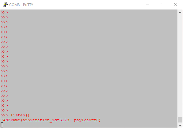
Different devices will receive different frame payloads. For example, the PyBoards in the test rig using the on-chip CAN controllers set to 75% sampling points see:
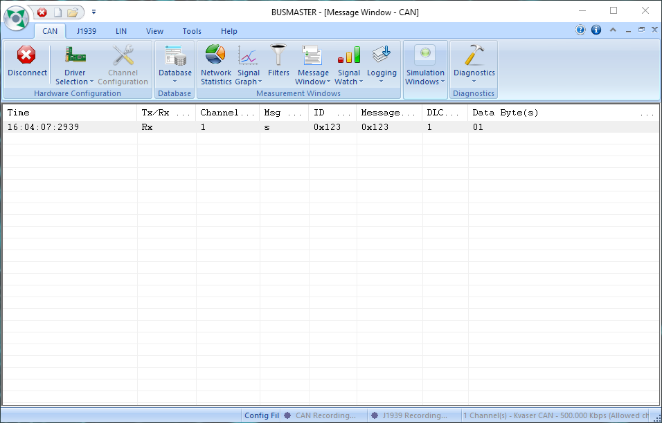
We set a Kvaser Leaf bus analyzer (controlled by the BUSMASTER PC software) to have a sample point of 50% and sees the other payload:
The logic analyzer view of the CAN frame shows how two payloads are encoded:
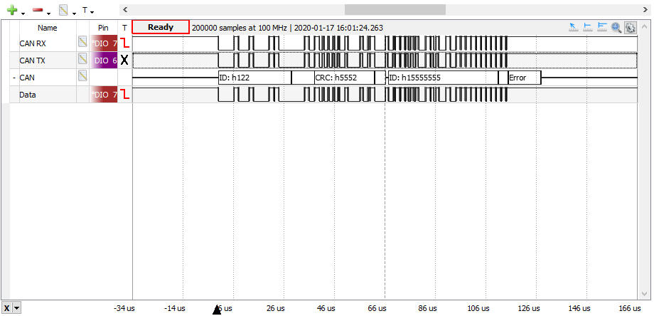
The protocol decoder in the Waveforms logic analyzer software has gone crazy because these are weird CAN bits and the decoder probably hasn’t seen anything like this before.
Zooming in on some of the bits shows the short dominant level sync interval at the start of each bit, and the different values inside some of the CAN bits:
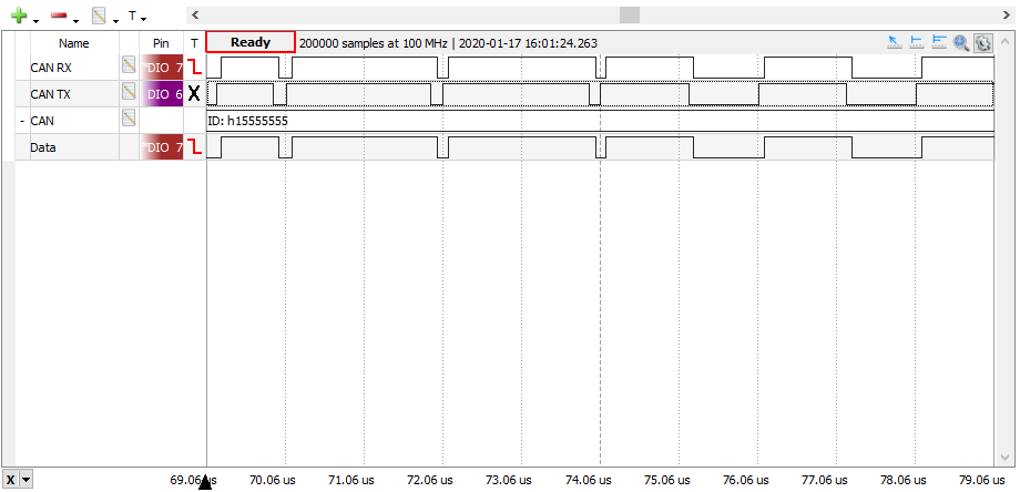
A Janus Frame Attack could be used to defeat an IDS that was doing ‘deep frame inspection’, looking at the payload to see if there is any attack (for example, looking inside diagnostic request frames). If the IDS has a sample point set differently to other CAN controllers then it can be made to see an innocent frame while a frame containing a malformed payload (e.g. to trigger a buffer overflow in a diagnostic software stack) could reach the target undetected.