
The Raspberry Pi Pico doesn’t have a CAN controller built-in but that’s no barrier: we can send CAN frames in software!
The CANHack toolkit is designed to demonstrate how the CAN protocol can be hacked at a low level if malware gets into a device on a CAN bus: it just needs an I/O port connected to a CAN transceiver.
The Raspberry Pi Pico is a new low-cost microcontroller board, using a new custom microcontroller, the RP2040. It doesn’t have a CAN controller but it’s widely available with lots of software and hardware support - so it’s the ideal platform to show off CAN bus. This is why we have moved away from the PyBoard and now the Pico is the official CANHack demonstrator platform!
In this blog post we will show how to build a CANHack system from a Raspberry Pi Pico. There’s some hardware to put together, and then some software to install.
Connecting up the hardware
First, a bill of materials:
- 1 Raspberry Pi Pico
- 1 Microchip MCP2562FD (PDF) CAN transceiver
- 2 100nF decoupling capacitors
- 1 9-pin D-sub male connector (if wanting to use CANOpen connectors)
To talk on a CAN bus all that’s strictly necessary is a CAN transceiver. This converts the CAN H/CAN L analog voltages into digital CAN RX/TX. Here We are going to show how to wire up a Microchip MCP2562FD transceiver. We use this transceiver because:
- We have a bunch in stock in our components store
- They come in PDIP packages that can be used directly on a breadboard
- They can be interfaced to 3.3V I/O
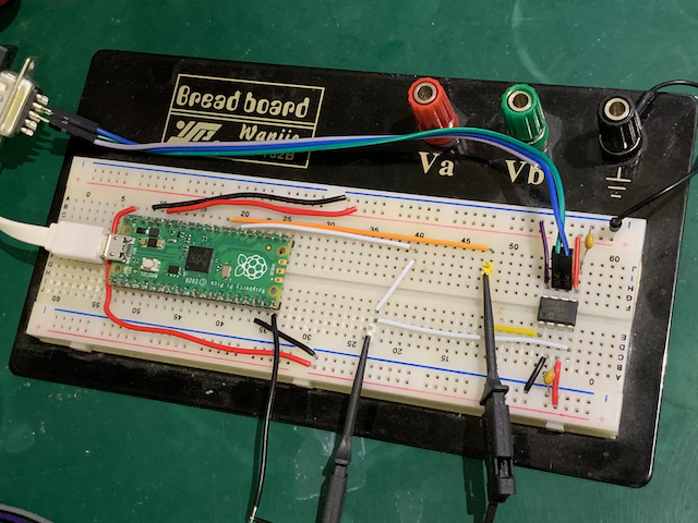
It’s important to use the right transceiver device: the variant with the VIO pin is needed because the device is powered by 5V but the Pico is a 3.3V board and the pins are not 5V-tolerant. So here’s our breadboard setup:
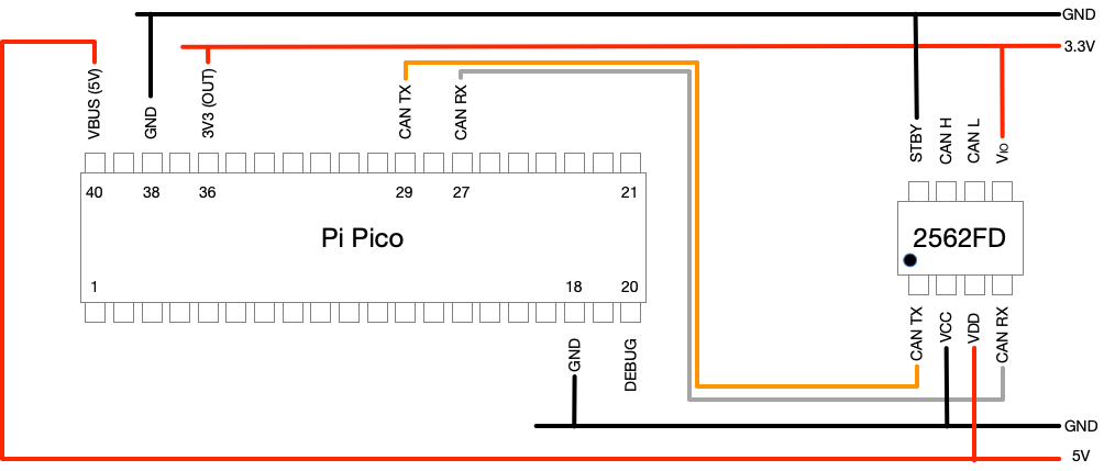
A schematic version of the above:
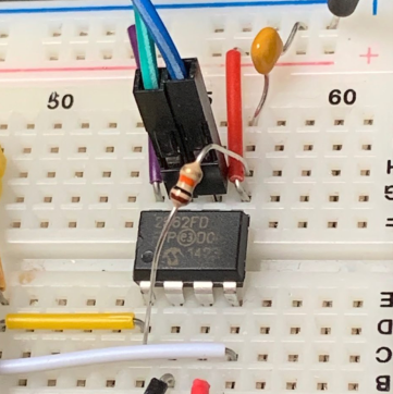
When the Pico boots its pins are in a high-impedance state and the CAN TX pin may therefore ‘float’ and could float to logic 0. To prevent this the MCP2562FD has an internal pull-up resistor between TX and VIO. However, in some cases this is not enough and an external resistor is added. We found that our breadboad setup sometimes had a TX glitch every 1ms so We put a 10K resistor between TX and VIO. This appears to work and we haven’t seen any more glitches since. The issue anyway goes away as soon as CANHack is initialized: it sets the TX pin to an output and drives it to 3.3V, but it’s best not to have these glitches ending up on the bus.
Even though the Pico is a 3.3V part, it does make 5V available on the VBUS pin, so there’s no need for a separate power supply for the transceiver. To be extra careful about not mixing 5V and 3.3V we used two separate power rails on the breadboard: the upper is 3.3V and the lower is 5V. The VIO pin on the transceiver is connected to 3.3V and that then makes the RX and TX digital lines operate at 3.3V. The STBY pin is for putting the transceiver into low power, but we don’t want to bother with that and tie it to ground.
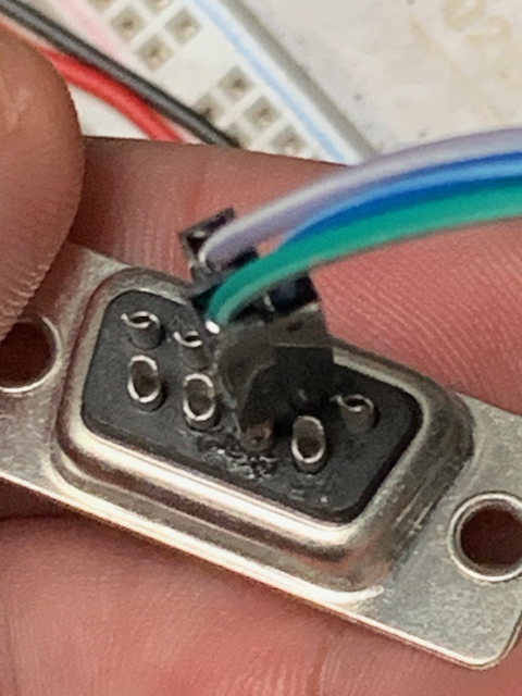
The CAN H/L pins of the transceiver are connected with jumper leads soldered into a 9-pin D-sub male connector (this is a standard CAN connector format, but they could just as easily be taken to an OBD-II connector). Green is CAN H (pin 7) and blue is CAN L (pin 2).
The I/O pins we chose to go with are GPIO 22 for CAN TX (pin 29 on the Pico) and GPIO 21 for CAN RX (pin 27 on the Pico). We also included a debug output on GPIO 15 (pin 20 on the Pico) - more about that later.
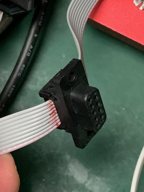
A few words about CAN bus wiring. For our benchtop CAN bus we use ribbon cable because it’s dead easy to snap on IDC connectors so that standard CAN connectors can be plugged together:
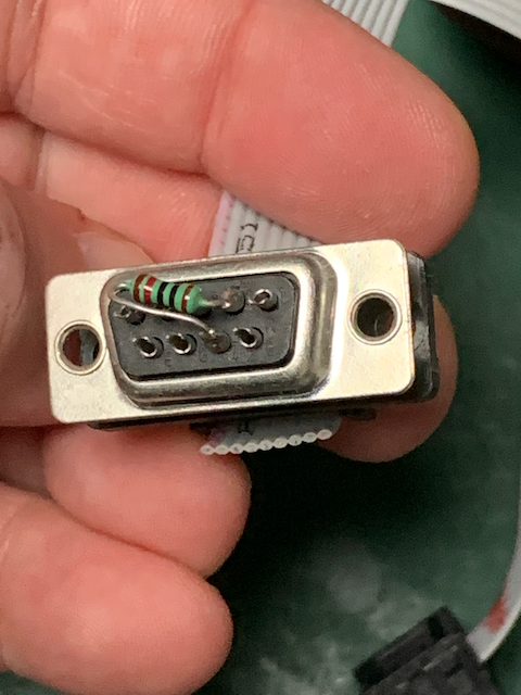
We use our own 120 ohm bus terminator resistors for either end of the bus cable:
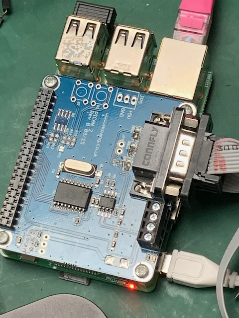
We also have a Raspberry Pi with a
PiCAN hat from SK Pang
and that has the
standard 9-pin D-sub connector. It runs Raspbian and
cantools. This is used as a victim board when doing bus hacking
as well as a source of CAN frames for testing and a simple bus analyzer.
Installing the software
CANHack is a set of C functions that bit-bang the CAN protocol using a simple free-running counter. But they need to be inside an execution environent to make them work. So we have developed a custom Python class in C for the MicroPython environment on the Pico. Then scripts can be written in Python that call the CANHack functions.
There’s a fairly steep learning curve for making custom classes on MicroPython, and the RP2040 has its own steep learning curve. We will cover these issues in a future blog post but for now we’ve made things easy by releasing a pre-built firmware image for MicroPython. This can be installed to the Pico by drag-and-drop of the firmware in the normal way:
- Press down the BOOTSEL button while powering up the board
- Drag and drop the firmware file
firmware.uf2to the folder that appears - Wait til the device reboots
The firmware is in the CANHack toolkit repository in pico/micropython.
The firmware adds a new class called CANHack to the module rp2 and
this can be accessed via the REPL command line in a terminal in the
normal way:
1
>>> ch = rp2.CANHack()
This initializes CANHack at the default 500kbit/sec baud rate (two other speeds are supported: 250kbit/sec and 125kbit/sec).
Putting it all together
So now that we have the hardware connected up and custom MicroPython firmware installed we can check that everthing works. So first let’s check the CAN TX pin is wired up.
Checking CAN TX
CAN TX can be tested by sending a ‘raw’ CAN frame on the bus. This simply transmits a bit pattern that will look like a CAN frame to receivers. First, let’s create that bit pattern:
1
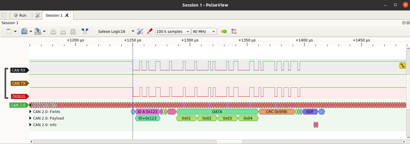
>>> ch.set_frame(can_id=0x14, data=bytes([1]))
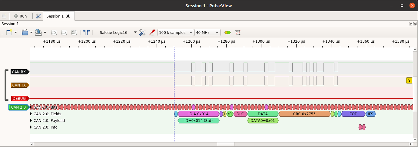
This creates a bit pattern for a CAN frame that’s the same as the one in the famous diagram in the Wikipedia page: a standard ID of 0x14 and a one byte payload.
The frame is pushed out of the CAN TX pin with the send_raw command:
1
>>> ch.send_raw()
As long as there isn’t any other traffic on the bus, this will be received
as a CAN frame by any controller connected to the bus. The candump tool
running on a Raspberry Pi with the PiCAN hat should show the frame turning
up (remember to match the baud rate: CANHack defaults to 500kbit/sec).
The function reports back a long list of numbers that are used to check the performance of the code.
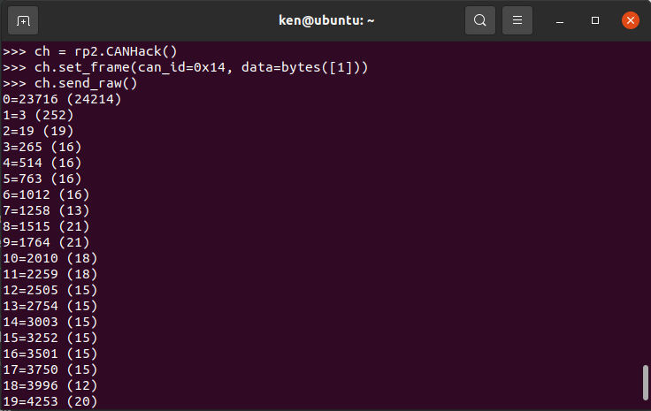
The numbers give the number of CPU cycles taken to react to a time event. They should be small (around 20 or smaller) and are largely dependent on the compile/link options used to build the firmware. The execute-in-place strategy of code that comes from external flash can’t be used with CANHack: there is a huge delay on fetching the code for the first time. The core parts of CANHack are pre-loaded into RAM on startup and execute from there with no cache delays. If the numbers are small then this linking/loading has worked properly.
Our breadboard contains test pins that we use to hook up a logic analyzer. We use a Saleae Logic16 with PulseView software from Sigrok, and our own CAN 2.0 protocol decoder. There are some very cheap (less than $10) logic analyzers for Sigrok’s PulseView and our decoder works with those just fine.
Testing CAN RX
If that all works then the CAN RX pin can be tested. There’s a function included in CANHack to push out to the debug pin (GPIO 15, Pico pin 20) what is received from CAN RX. This is activated with:
1
>>> ch.loopback()
It waits for a falling edge on CAN RX and then will then reflect to the
debug pin what whatever it sees on CAN RX for 160 bit times (enough to
reflect a complete CAN frame). The best way to use this is to put a logic
analyzer on to the debug pin
and then send a CAN frame from another device (e.g. use cansend on
a Raspberry Pi) and then see if the debug pin shows that frame:
Sending a CAN frame
CANHack has the ability to send a CAN frame according to the CAN protocol
(entering arbitration, backing off if it loses arbitration or detects an
error). The send_frame call does that. For example:
1
2
>>> ch.set_frame(can_id=0x100, extended=True, data=bytes([0xde, 0xad, 0xbe, 0xef]))
>>> ch.send_frame()
That sends an extended ID CAN frame on the bus with a payload of 0xdeadbeef.
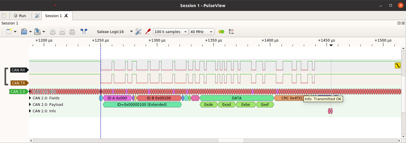
By default the function returns if it loses arbitration or there is an error while transmitting a frame.
A working CANHack system
If you’ve got this far then you have a working CANHack system. Congratulations! Next up we will be writing about how to use this hardware to demonstrate protocol attacks on CAN.
